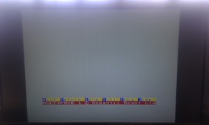
The Issue 2 nightmare…. the bad display.
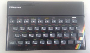
Many people know there are more than a few types of Spectrum. The most obvious type is the rubber-keyed fellow. Let us bask in its glory for a moment.
Finished basking? Great. What many people don’t know is that all rubbery Spectrums were not created equal. There are four types, referred to as issues. An Issue 1 Spectrum is rare, about 16,000 were made. Issue 2 Spectrums are more common, about 120,000 I estimate, Issue 3 Spectrums are dead common, and Issue 4 Spectrums are scarce unless they’re “Spectrum+” machines.
What we’re going to deal with today is the Issue 2 Spectrum. It all applies to Issue 1 Spectrums too, but not issue 3 as Sir Clive had got things sorted a bit better by then.
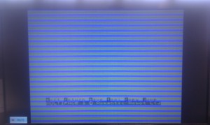
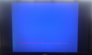
If your Spectrum looks like this:
You may be thinking you poor trusty Speccy has gone to meet its maker (Sir Clive, in this case). However, all is not lost!
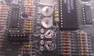
There are a set of dials in your Spectrum. They’re not in Issue 3 or above as they’re not necessary, but before then they control the picture. Seek ye these four dials:
Look innocent, don’t they? They are TC1, TC2, VR1, VR2 from top to bottom.
Actually, one of them is. The top one, see that? That is a very fine tuning one which doesn’t affect things much. It actually detunes things very slightly to get rid of the ripply affect you see on the characters on the display. You can tweak this as a final thing.
Before that, though, we need to get the thing displaying.
The 48K Spectrum Service manual says the voltage across pin 3 to pin 2 of IC14 should be 75mV +/- 20mV, and from pin 3 to pin 4 should be 130mV +/- 20mV. The VR1 affects pin 4, the VR2 affects pin 2.
However, if you actually set it to these voltages, it probably still won’t be right. However, they’ll be close.
Now comes the biggest problem, though – everything’s changed since the Spectrum was made. Interference is usually rife in 0ld Spectrums, and tolerances are everywhere after 30 years. Here’s a quick/dirty guide to dialling your Spectrum in:
- Set the voltage from pin 3 to pin 4 to be about 130mV using VR1.
- Set the voltage from pin 3 to pin 2 to be about 75mV using VR2.
- Twiddle TC2 (it goes right round, and doesn’t stop turning) until it looks about right.
- Turn VR1 very slightly.
- Turn VR2 a bit in either direction.
- Go to step 4 until satisfied, trying not to go too far from the original positions.
You may well find it’s nice now. If so: yay! You now have a nice Spectrum. If not, you have a headache.
So, here come some tips for getting your Spectrum Issue 2 displaying as it should….
- Convert it to composite video! Take out as many variables as possible, including the TV tuning.
- Replace all the electrolytic capacitors. There’s not many of them and they’re mostly 22uF. They were never meant to be in use for so long, so don’t smooth the circuit properly, introducing interference and making dialling in rather awkward.
- Replace the 7805 regulator. They pump out interference all over the board; doesn’t really help much. A new one will be much better sometimes.
- Replace TR2 and TR3, both ZTX313 transistors. You can use 2N2369 too but it may not be quite as clean a signal.
- Replace the 4.43MHz crystal as this is the colour carrier.
- Replace the VR1 and/or VR2 variable resistors.
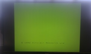
When all this is done, you should have a nice picture such as below:
Obviously if you don’t have a multiface triggered you won’t get the colours, but they make useful test signals.
Hey presto! A working Spectrum!
